Working principle
A single-phase diode rectifier converts an AC voltage at the input to a DC voltage at the output. The power flow in the circuit is unidirectional, i.e., from the AC input to the DC output only. This is a full bridge rectifier since it has two pairs of diodes. The circuit operation depends on the state of the voltage source (Ls, Rs and Ld are neglected for simplicity):
- Positive half cycle: The diodes D1 and D2 conduct while diodes D3 and D4 are blocking. The positive grid voltage induces a positive voltage across the load resistance.
- Negative half cycle: Now diodes D3 and D4 conduct while diodes D1 and D2 are blocking. Since a positive current flows through diodes D3 and D4 the voltage across the resistor is again positive.
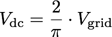
The combination of the four diodes achieves a full wave rectification of the AC input voltage with an average DC voltage of:
Influence of inductors
During the positive half cycle of the grid voltage the diode pair D1/D2 conducts. As the DC voltage crosses zero both diode pairs D1/D2 and D3/D4 conduct since the inductors Ls and Ld try to maintain the current flow. The time during which both diode pairs conduct is called the current commutation interval. All four diodes have zero forward voltage so during the current commutation between the two diode pairs the DC voltage stays zero.
The series combination of Ld and Rd acts as a first order low pass filter that reduces the voltage ripple at the output.
Experiments
- Change the source inductance from 100 µH to 500 µH and observe the increase of the current commutation interval.
- Change the load inductance from 20 mH to 100 mH and observe the reduction in the ripple of the output voltage.