This PLECS demo model shows the effects of measurement error and mechanical resonance on the performance of an electric vehicle (EV) system. A possible controls solution to mitigate the observed issue is provided and the overall system performance can be compared before and after the method is added.
Vehicle model
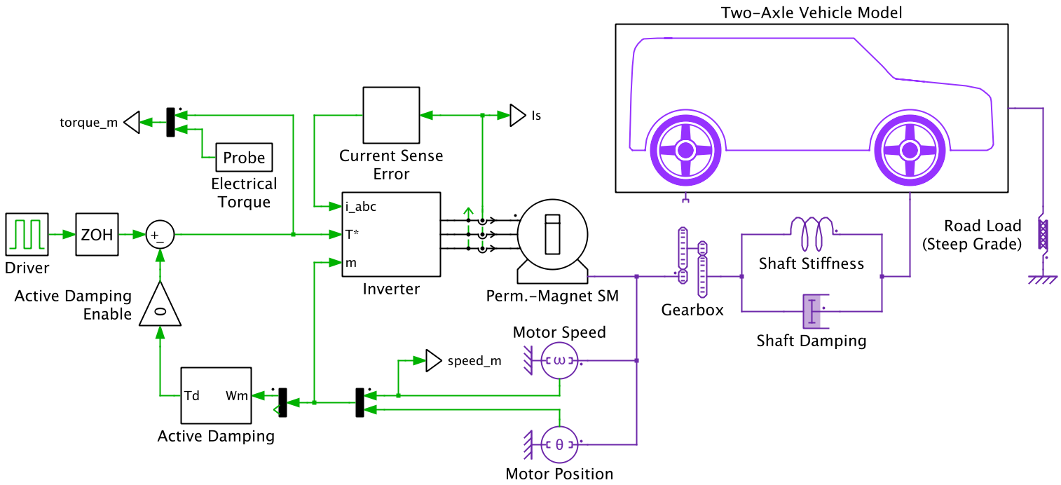
The front-wheel drive EV implementation is based on two slip-based wheel models. The EV is propelled by a wye-connected permanent magnet synchronous machine (PMSM) attached to a single-speed gearbox. The damping and stiffness properties of the half-shafts connecting the gearbox and differential to the front wheels of the EV are incorporated in the system model.
Power electronic system

An ideal DC voltage source is used to model a battery pack supplying energy to the vehicle. The battery is connected to the DC-side of a two-level voltage source inverter that drives the PMSM.
A basic torque controller is implemented to convert the torque demand to current setpoints in the rotor reference frame (DQ). The current setpoints along with measured alpha-beta (αβ) currents, rotor position, and the DC voltage are fed into a digital synchronous frame regulator. The regulator generates a voltage setpoint that is transformed into the αβ reference frame. A space vector modulator is then used to translate this voltage setpoint into switching signals for the two-level converter.
System non-idealities
A sudden step change in the motor torque leads to an oscillation of the motor inertia. This windup effect occurs due to excitation of a natural frequency of the powertrain, which is a function of the stiffness coefficient of the shaft, the rotor inertia of the motor, and the gear ratio.
When modeling electric drives it is often assumed that all measurements are ideal and accurate. However, in reality some amount of offset and gain errors will be present in all sensors. It can be shown that gain errors of the current measurement can lead to torque oscillation at twice the fundamental frequency of the phase currents. This causes a torque ripple, which can excite the natural frequency of the mechanical system as described above and reduce vehicle driveability.
Simulation
Windup and measurement error effects
The windup effects caused by a step change in motor torque during startup, and the sustained oscillation excited by a steady-state current sensor error, are easily observed. As an example, a gain error in the measurement of two of the phase currents can be modeled, where one phase current is overestimated by 5% and the other is underestimated by 5%. This will lead to a low frequency oscillation of the generated motor torque, which translates to a low frequency oscillation in the motor speed.
Active damping
A solution is provided to minimize drivetrain oscillations that actively controls the torque demand on the PMSM. With this method, the rotor speed is measured and fed into an outer speed control loop. This outer control loop consists of a digital PI controller with an anti-windup mechanism that generates a correction torque from the measured rotor speed. This correction torque, along with the torque demand of the driver, is used to modify the torque setpoint that is fed into the torque controller. The outer speed control loop adjusts the torque demand signal that is fed into the torque controller, resulting in a significant reduction in the windup effects that occur without damping.
Additionally, the low frequency oscillation of the motor speed arising due to the measurement error of the current sensor is also actively damped by the outer speed control loop. The feedback of the motor speed results in a low frequency adjustment in the steady-state torque demand setpoint. This translates to a reduction in the amplitude of the motor's peak-to-peak low frequency speed oscillation.
Low speed versus high speed effects
The maximum steady-state powertrain oscillation (due to current sensor error) occurs when the motor torque excites the natural frequency (f0) of the system. A deviation away from the speed (v0) at which this occurs reduces the steady-state speed oscillation. The simple active damping algorithm provided is able to reduce these oscillations for a vehicle moving at any speed, including v0.
Try it
This model is available in the PLECS Demo Model library provided in both versions of PLECS.