This PLECS demo model shows a two-phase series capacitor buck converter circuit with constant on-time control as proposed by Texas Instruments in the white paper "Design of a high-frequency series capacitor buck converter."
Power Circuit
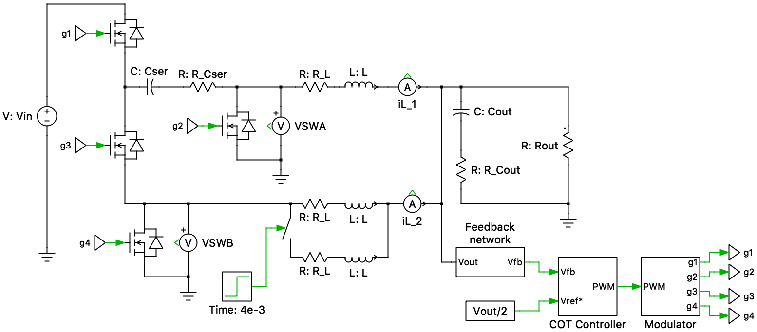
The series capacitor buck converter is a DC/DC topology combining a switched capacitor circuit and a two-phase buck converter into a single-stage. The series capacitor (whose voltage is half the input voltage nominally) provides a 2-to-1 voltage step-down. From the perspective of the output filter, it looks like a buck converter with half the input voltage. The switch nodes (VSWA and VSWB) see only half the input voltage instead of the full input voltage in a buck converter, reducing the switching loss.
This topology automatically balances inductor currents without any current sensing circuits or load-sharing control loops. The converter has a 50 percent duty-cycle limitation, which combined with the inherent 2-to-1 voltage step-down created by the series capacitor, dictates the maximum possible output voltage to be one-fourth the input voltage. The practical limit of the output voltage may be one-fifth the input voltage. In the current demo, the desired output voltage is one-tenth the input voltage.
Control
The output voltage of the circuit is regulated by using constant on-time (COT) control. This is a variable frequency solution where the on-time is held constant. The control uses the output voltage ripple (Vfb) as a PWM ramp signal. This signal is compared to the reference (Vref*), therefore, some output voltage ripple is required. This is provided by the output capacitor ESR. The comparator monitors the feedback voltage (Vfb) and triggers a high side switch on-time when the feedback output is lower than the reference value. The controller only modulates the switch-off time, since the on-time is held constant. Additionally, a Minimum Off-time block prevents inductor saturation during a rapid change of load. COT control is particularly beneficial for large voltage step-downs (low duty cycle).
A COT implementation using the PLECS State Machine block is shown in the demo model Buck Converter with State Machine-Based Constant On-Time Controller.
Simulation
The model has been configured to demonstrate the steady-state operation of the converter for a 12 V input point of load (POL) voltage-regulator application. The average series capacitor voltage is approximately half the input voltage (6 V), the load voltage is approximately one-tenth the input voltage (1.2 V) and both the switch node voltages, VSWA and VSWB, are limited to half the input voltage (6 V). Additionally, the inductor currents are perfectly balanced and this can be demonstrated by varying the value of one of the inductors.
Try it
This model is available in the PLECS Demo Model library provided in both versions of PLECS.