Working principle
The multivibrator amplifier is an astable oscillator which generates rectangular waveforms at the output using an RC network at the inverting input and a voltage divider at the non-inverting input of the amplifier.
This configuration switches between its two unstable states, with the time spent in each state controlled by the charging or discharging of the capacitor through a resistor.
Initially, the capacitor starts charging up to Vout. Once the voltage at the inverting terminal becomes equal to or greater than the voltage at the non-inverting terminal, λVout, the op-amp output clamps to the negative supply rail, thus causing the capacitor charge go to zero and start charging to the new value of Vout. This goes on until the negative supply rail reaches the -λVout threshold, and the output changes state again, reinitiating the cycle. This produces a steady, continuous square wave pulse train at the output.
The RC time constant determines the rate of capacitor charge/discharge, or the period of the output waveform, and the voltage divider network sets the reference voltage level, λVout.
A small capacitance Cin is required for decoupling of negative feedback.
Formula derivation
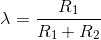
From voltage divider,
General charging equation for a capacitor with an original charge:

For V = Vout and q0 = λCVout,

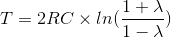
This result is also obtained for the discharging period of the operation, assuming the magnitudes of the op-amp’s rails are equal, meaning tcharge = tdischarge.
Multivibrators are used in a variety of applications where square waves or timed intervals are required, such as a flashing light.
Experiments
- Increase the capacitance value to 1 uF and observe the increase in the amount of time it takes to charge up the capacitor.
- Increase R2 to 50 kΩ and observe the change in the output voltage switching frequency.