Multi-Core Processing for Complex Models
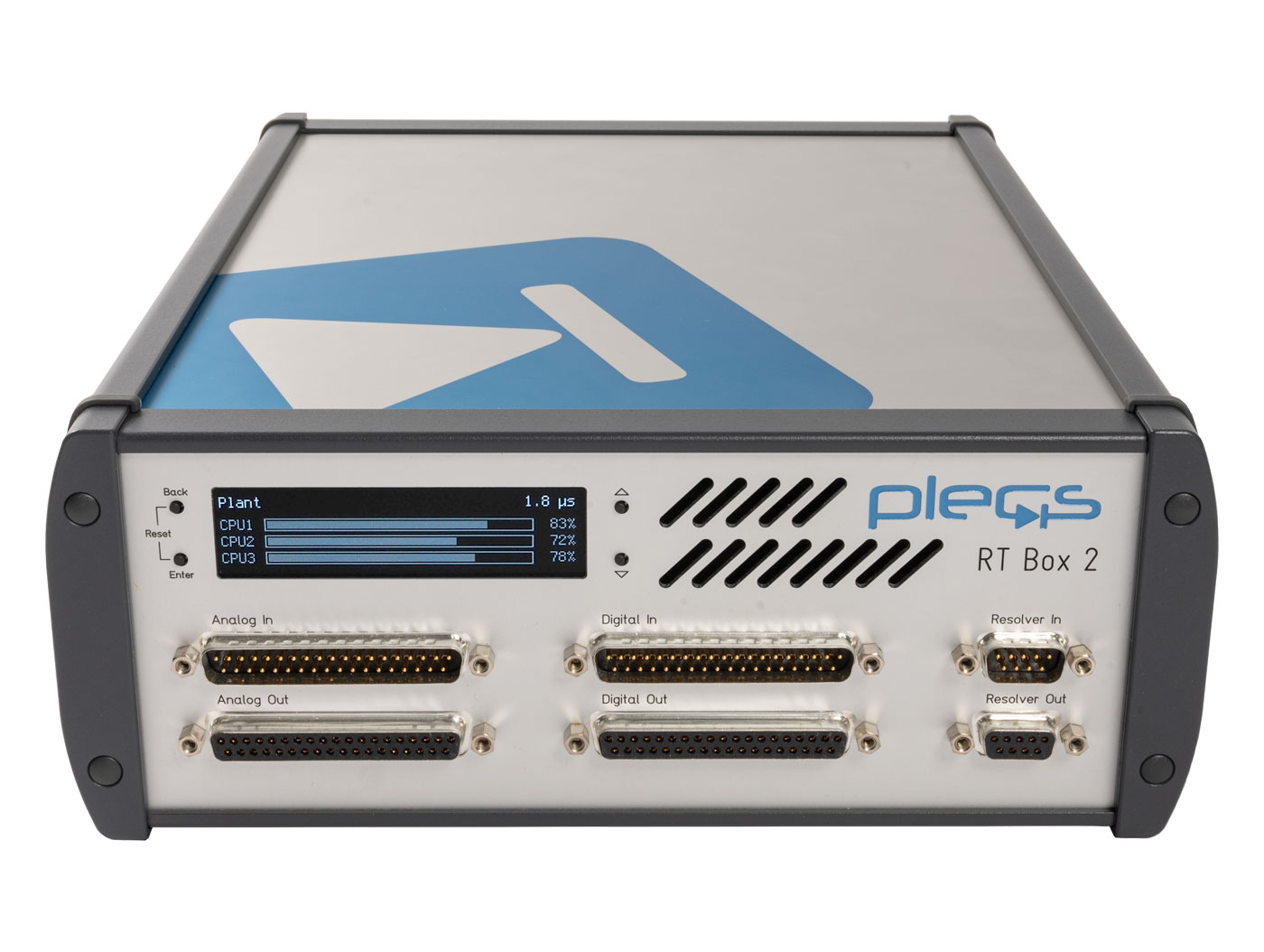
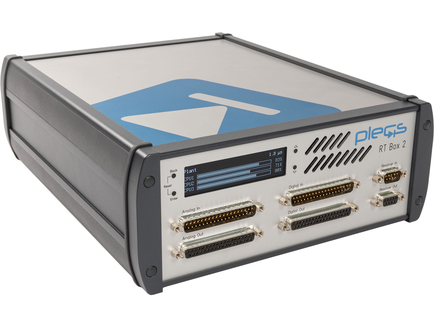
The RT Box 2 speeds up the simulation of complex models of power electronics circuits. Models that can be split into separate physical sub-systems will benefit from the parallel processing capability. The RT Box 2 also offers additional analog and digital interfaces plus a solid-state drive for data storage.
If you are looking for a real-time simulator with more analog and digital I/Os, you might want to consider the RT Box 3.
Processor
The RT Box 2 employs the latest generation Xilinx Zynq Ultrascale+ multiprocessor system-on-chip. Of its four Cortex-A53 CPU cores, up to three can be used for real-time simulation calculations, while the remaining core runs an embedded Linux for communication and ancillary services. The FPGA inside the Zynq Ultrascale+ is currently used to control the analog data converters and the the digital I/Os. With future releases of the PLECS Coder and the RT Box firmware, the user will be able to compute parts of the simulation model with time-steps in the sub-microsecond range on the FPGA.
Analog I/O
Compared to the RT Box 1, the maximum sample rate of the analog I/Os has been increased to 5 Msps and the settling time of the analog outputs has been halved to 0.5 µs.
Resolver I/O
When used for HIL simulation, the RT Box 2 can emulate a magnetic resolver with an analog bandwidth of up to 10 MHz. The RT Box 2 also features a resolver-to-digital converter for position evaluation in control application.
Technical Specifications
| Processor | Xilinx Zynq Ultrascale+ | ZU9EG |
| CPU cores | 4 x ARM Cortex-A53, 1.5 GHz | |
| Analog inputs | Channels | 16 |
| Resolution | 16 bit, simultaneous sampling | |
| Voltage ranges | -10 ... 10 V -5 ... 5 V |
|
| Input type | Differential | |
| Max. sample rate | 5 Msps | |
| Input impedance | 1 MΩ, 24 pF | |
| Connector | D-SUB 37 pin male | |
| Analog outputs | Channels | 16 |
| Resolution | 16 bit, simultaneous update | |
| Voltage ranges | -10 ... 10 V 0 ... 10 V -5 ... 5 V 0 ... 5 V |
|
| Max. update rate | 5 Msps | |
| Output impedance | 0 Ω | |
| Max. output current | 10 mA | |
| Connector | D-SUB 37 pin female | |
| Digital inputs | Channels | 32 |
| Logic levels | 3.3 V (5 V tolerant) | |
| Connector | D-SUB 37 pin male | |
| Digital outputs | Channels | 32 |
| Logic levels | 3.3 V 5 V |
|
| Connector | D-SUB 37 pin female | |
| Resolver | Input/Output | 1/1 |
| Connector | D-SUB 9 pin male/fem. | |
| I/O protection | Short-circuit | Permanent |
| Overvoltage | -24 ... 24 V | |
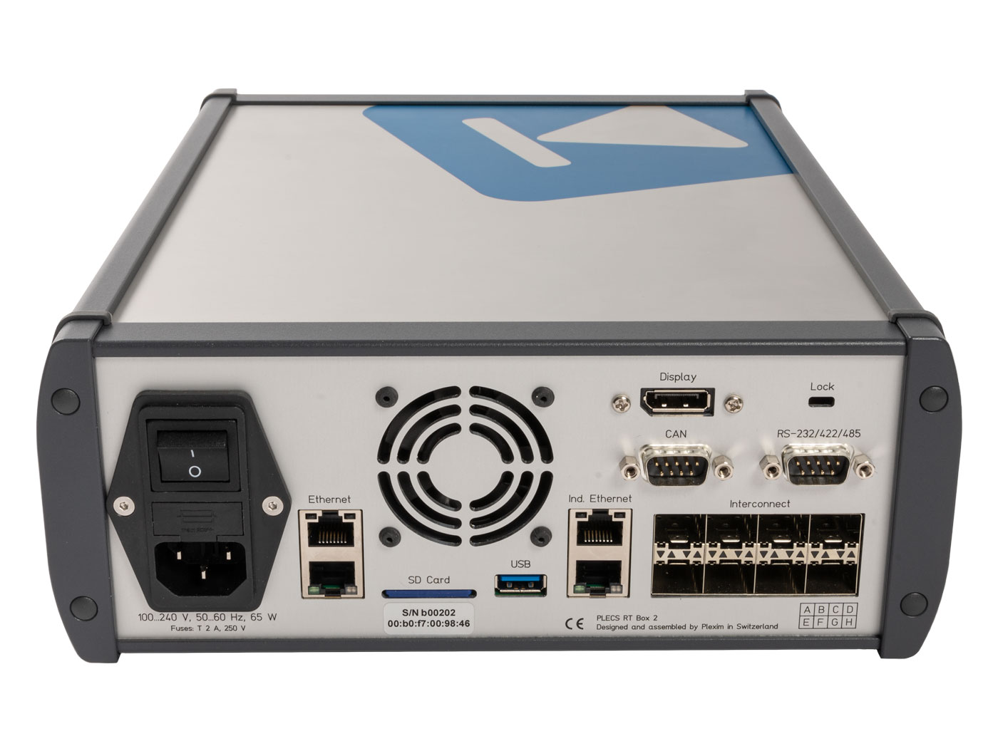
| Connectivity | Gigabit Ethernet | 2 |
| SFP+ interconnects 6.25 Gbps per lane |
8 | |
| Industrial Ethernet | 2 (EtherCAT) | |
| CAN bus | 2 | |
| RS 232/422/485 | 2 | |
| USB A 3.0 | 1 | |
| DisplayPort | 1 | |
| Storage | Internal SSD | 480 GB |
| Firmware | SD card | |
| Power supply (internal) |
100 ... 240 Vac 50 ... 60 Hz |
65 VA |
| Size (mm) | Depth x Width | 310 x 250 |
| Height | 100 |