Multi-Core Processing for Complex Models
The RT Box 2 speeds up the simulation of complex models of power electronics circuits. Models that can be split into separate physical sub-systems will benefit from the parallel processing capability. The RT Box 2 also offers a second Nanostep® solver unit along with the faster FPGA-based simulation of various circuit elements, additional analog and digital interfaces plus a solid-state drive for data storage.
If you are looking for a real-time simulator with more analog and digital I/Os, you might want to consider the RT Box 3.
Processor
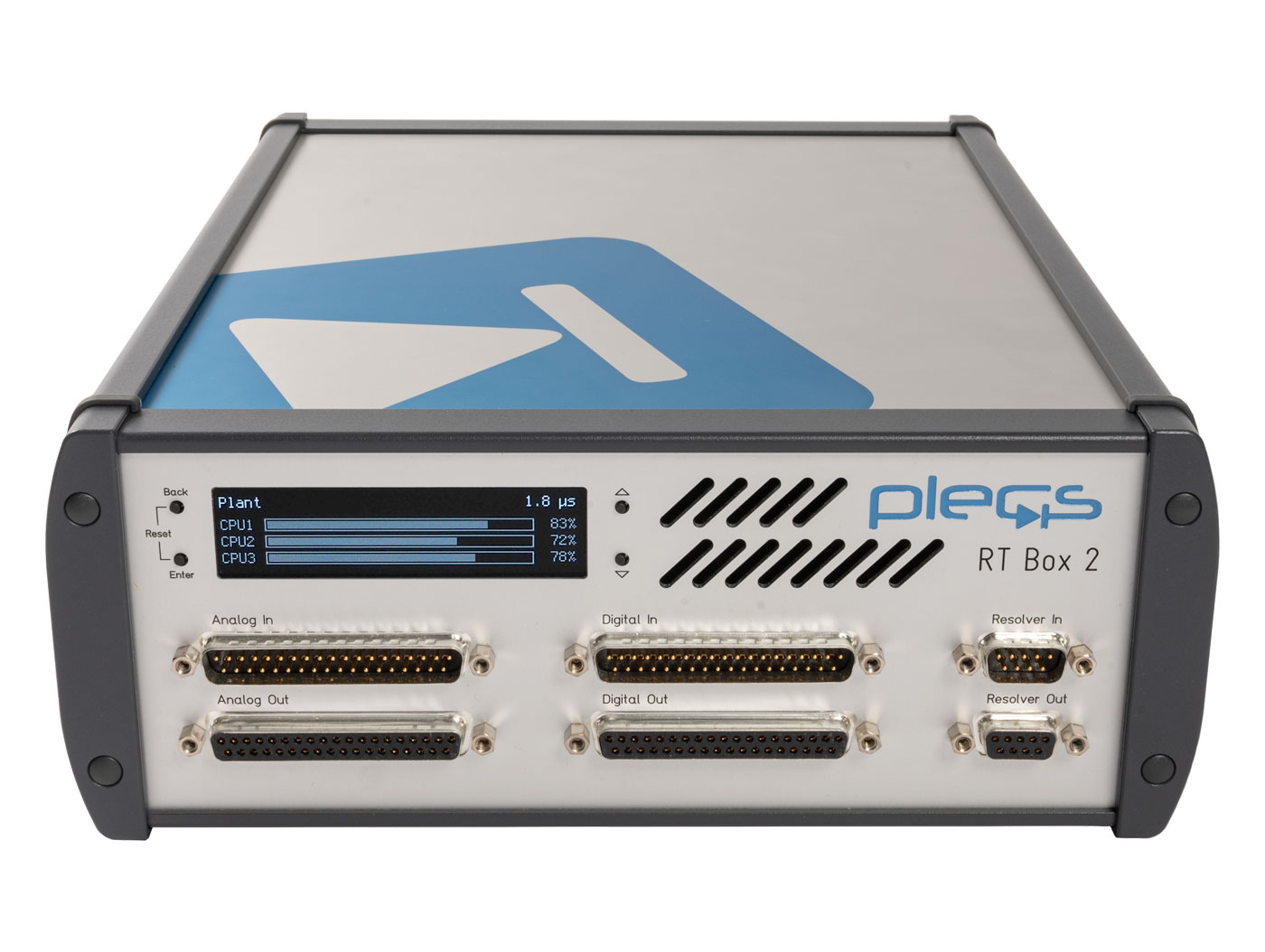
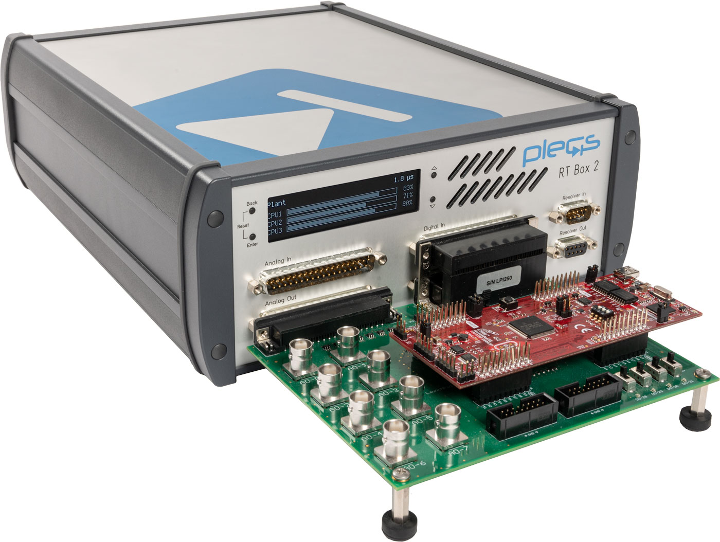
The RT Box 2 employs the latest generation Xilinx Zynq Ultrascale+ multiprocessor system-on-chip. Of its four Cortex-A53 CPU cores, up to three can be used for real-time simulation calculations, while the remaining core runs an embedded Linux for communication and ancillary services. The FPGA inside the Zynq Ultrascale+ is used to control the analog data converters and the the digital I/Os. With the latest release of the PLECS Coder and the RT Box firmware, the user can simulate specific power stages using the included pair of Nanostep solver units, and compute the additional parts of the simulation model with time-steps in the sub-microsecond range on the FPGA, or in the microsecond range on the CPU.
Analog I/O
Compared to the RT Box 1, the maximum sample rate of the analog I/Os has been increased to 5 Msps and the settling time of the analog outputs has been halved to 0.5 µs.
Resolver I/O
When used for HIL simulation, the RT Box 2 can emulate a magnetic resolver with an analog bandwidth of up to 10 MHz. The RT Box 2 also features a resolver-to-digital converter for position evaluation in control application.
Technical Specifications
| Processor | Xilinx Zynq Ultrascale+ | ZU9EG |
| CPU cores | 4 x ARM Cortex-A53, 1.5 GHz | |
| Nanostep® solver | Units | 2 |
| Step size | 4 ns | |
| Analog inputs | Channels | 16 |
| Resolution | 16 bit, simultaneous sampling | |
| Voltage ranges | -10 ... 10 V -5 ... 5 V |
|
| Input type | Differential | |
| Max. sample rate | 5 Msps | |
| Input impedance | 1 MΩ, 24 pF | |
| Connector | D-SUB 37 pin male | |
| Analog outputs | Channels | 16 |
| Resolution | 16 bit, simultaneous update | |
| Voltage ranges | -10 ... 10 V 0 ... 10 V -5 ... 5 V 0 ... 5 V |
|
| Max. update rate | 5 Msps | |
| Output impedance | 0 Ω | |
| Max. output current | 10 mA | |
| Connector | D-SUB 37 pin female | |
| Digital inputs | Channels | 32 |
| Logic levels | 3.3 V (5 V tolerant) | |
| Connector | D-SUB 37 pin male | |
| Digital outputs | Channels | 32 |
| Logic levels | 3.3 V 5 V |
|
| Connector | D-SUB 37 pin female | |
| Resolver | Input/Output | 1/1 |
| Connector | D-SUB 9 pin male/fem. | |
| I/O protection | Short-circuit | Permanent |
| Overvoltage | -24 ... 24 V | |
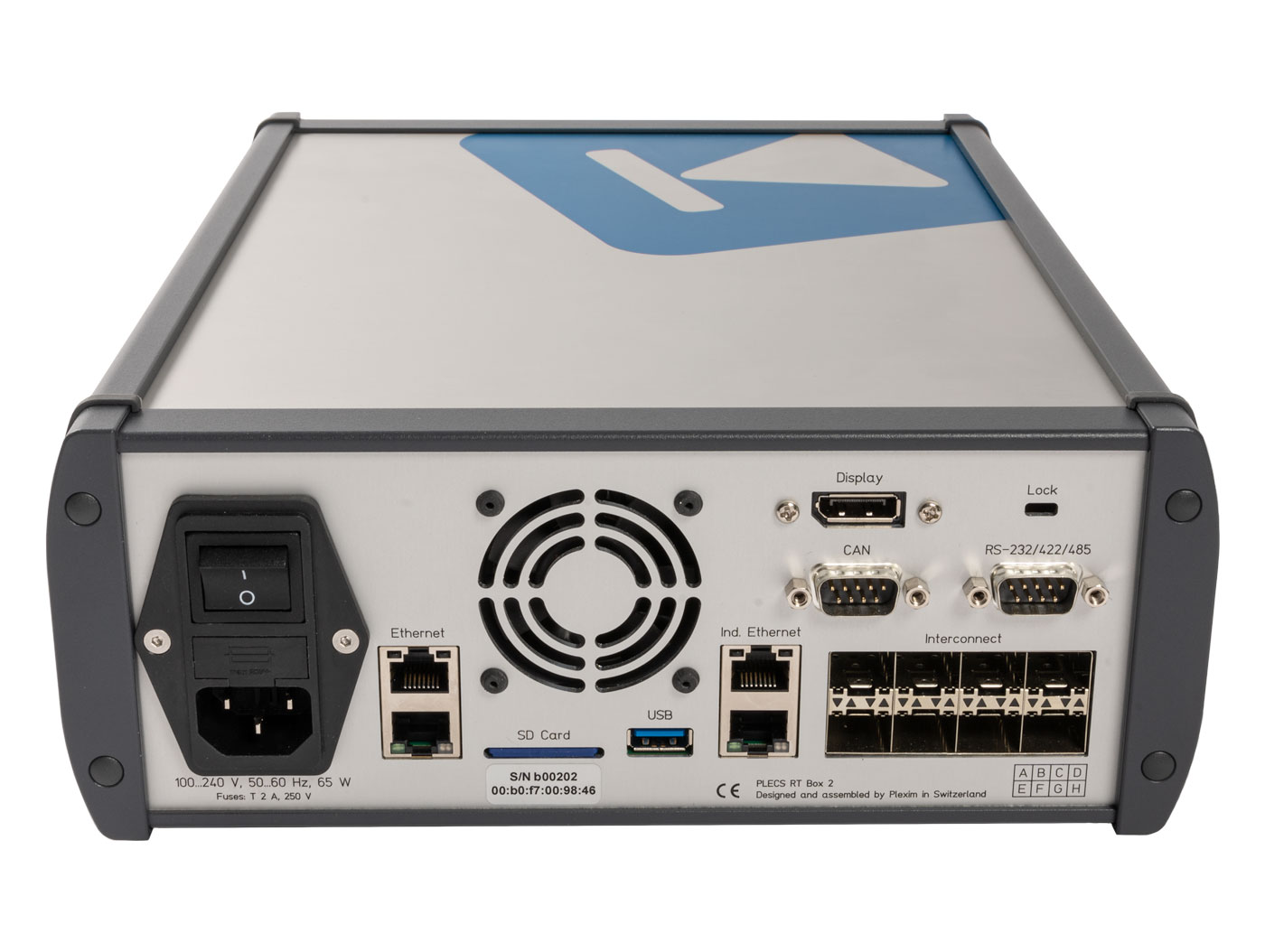
| Connectivity | Gigabit Ethernet | 2 |
| SFP+ interconnects 6.25 Gbps per lane |
8 | |
| Industrial Ethernet | 2 (EtherCAT) | |
| CAN bus | 2 | |
| RS 232/422/485 | 2 | |
| USB A 3.0 | 1 | |
| DisplayPort | 1 | |
| Storage | Internal SSD | 480 GB |
| Firmware | SD card | |
| Power supply (internal) |
100 ... 240 Vac 50 ... 60 Hz |
65 VA |
| Size (mm) | Depth x Width | 310 x 250 |
| Height | 100 |