This PLECS demo model shows a medium-voltage static synchronous compensator (STATCOM) system. Converters with cascaded connections are common in high-power applications such as medium-voltage drives, high-voltage direct current (HVDC) and flexible alternating current transmission systems (FACTS). These types of converters have the advantages of low switching losses and high redundancy, but require sophisticated control, e.g., cell-capacitor voltage balancing. The STATCOM’s purpose is to compensate for the reactive power required by various loads on a power system.
Power circuit
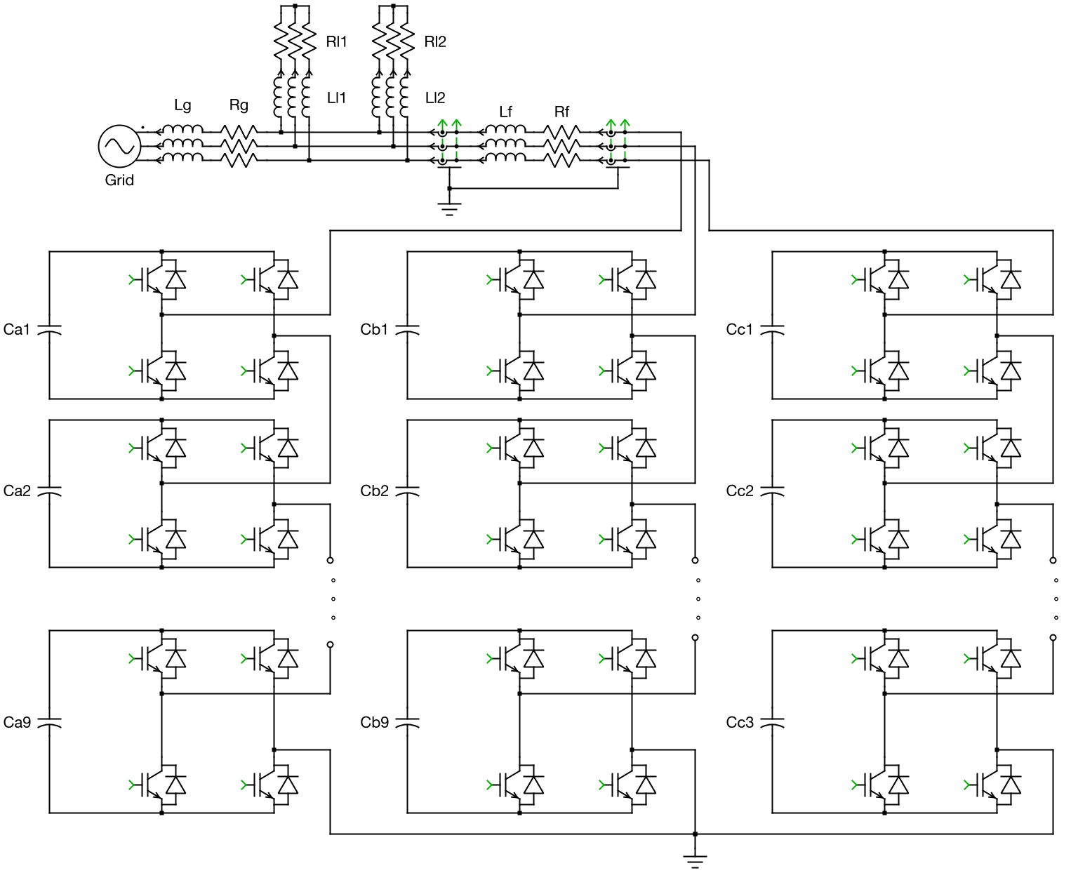
There are separate H-bridge circuits in this system for phases A, B, and C, respectively. Each phase consists of 9 H-bridge cells connected in series, forming a "cluster". The clusters are connected to the medium-voltage (MV) grid via an inductive filter, Lf, and its winding resistance, Rf. The 50 Hz, MV grid is modeled as an ideal AC voltage source with a line-to-line RMS voltage of 15 kV. The inductance, Lg, and resistance, Rg, represent the equivalent grid impedance. Connected to the grid are two different passive R-L loads (Rl1, Ll1 and Rl2, Ll2).
The H-bridge cells utilize conventional IGBTs. These are modeled as ideal switches in PLECS to achieve high speed and robustness for system-level simulation. During the simulation, different switching combinations of the individual devices vary the magnitude of the capacitive voltage source feeding the grid. The converter provides reactive current to the utility when its terminal voltage magnitude is greater than that of the grid, and sinks reactive power with a lower voltage magnitude, as compared to the grid.
The IGBT Full Bridge power module library component is used to model the converter. This component has two configurations: a Switched implementation where ideal switches represent the semiconductors, and an Averaged configuration that uses controlled voltage and current sources. The power module also has a parameter setting for the number of series-connected cells. The implementation of both the power module and the controller is such that the number of cells can be configured at the top level without having to extend the model with additional wiring or components. Further, this model uses the Switched implementation of the power module components. Note that increasing the number of cells will slow down the simulation and the use of the Averaged implementation is therefore recommended when modeling higher numbers of cells.
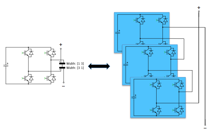
To make the schematic concise and organized, the IGBTs and DC capacitors are vectorized, instead of displaying 27 cells (9 cells per leg) in the same schematic. The Wire Multiplexer block enables a series connection of 9 cells for each of the three legs, resulting in only one H-bridge being visible for each cluster. The figure below demonstrates the concept of vectorization (of three cells for simplicity). However, keep in mind that, the number of IGBTs and DC capacitors is unaffected by the vectorization and thus there is no effect on simulation speed using this technique. Also, if one capacitor is dragged into the "Probe" block for observing its voltage, multiple waveforms will be displayed in the Scope.
Control
The control scheme of the STATCOM is tasked with generating the desired amount of reactive power at the grid terminal and maintaining the mean value of the cell capacitors’ voltage at a defined constant level. As the figure below depicts, the top-level control is composed of two loops. The voltage controller is the outer loop. It compares the reference set point and measurement of the cell capacitors’ voltage mean value, and provides the reference value for the inner current loop via a PI controller with an anti-windup scheme. The inner current loop is implemented in the rotational reference framework, and is synchronized to the AC terminal voltage. The reference of the d-axis component comes from the voltage controller, while that of the q-axis component is directly calculated from the desired reactive power. The outputs of the current controllers in both the d- and q-axes are transformed back to ABC coordinates, and are normalized by the single cell capacitor voltage times the number of cells per cluster (9). The resulting values are used further on as modulation indices for the PWM generation.
PWM Generation
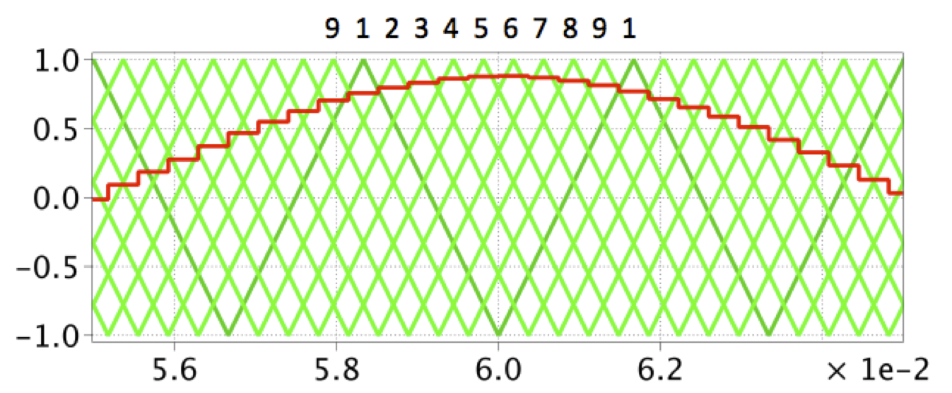
The switching signals of the H-bridges are generated by comparing the modulation index with triangular carrier waves of 300 Hz. For one cluster, the carriers for the cells 1 − 9 are interleaved by 40 degrees, as shown in the following figure. In this way, a 9-level output voltage can be achieved, which reduces the harmonic distortion significantly.
Cell Capacitor Voltage Balancing
The interleaved modulation does not automatically guarantee that the amount of reactive power from the grid terminal is homogeneously distributed among all cell capacitors, and therefore they will be charged and discharged at different rates. This will result in unacceptable voltage imbalances. To avoid this undesired situation, the modulation indices of individual cells need to be modified from the set point provided by the outer control loop. The voltage balancing is carried out in two stages: the lower level scheme keeps the voltage of the 9 cells within one cluster at their mean values (known as individual balancing), while the secondary scheme ensures the mean voltage of all capacitors in a cluster is equal to the mean voltage for 3 clusters. The latter serves to eliminate the effect of asymmetry, for example on cable impedance (known as cluster balancing).
Simulation
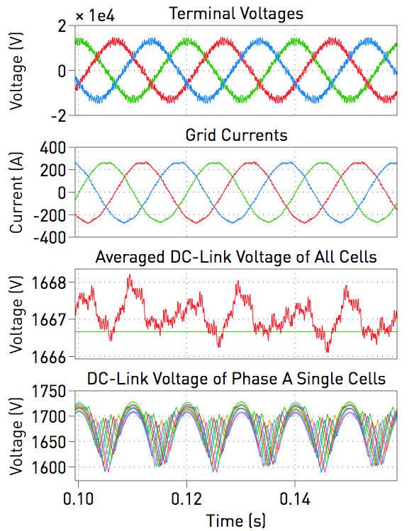
The simulated load terminal voltage, grid current, averaged value and single values of the DC-link capacitor voltages are displayed below for the 9-level converter. The model also allows for system analysis such as observing the effects of the cell balancing algorithm. Additionally, the system complexity as driven by the number of cells is easily configured in the model's initialization script, and the resulting effect on the simulation speed can be seen.
Try it
This model is available in the PLECS Demo Model library provided in both versions of PLECS.