Working principle
According to Kirchoff’s Voltage Law (KVL), the sum of all voltages around a loop is equal to zero. When going around the loop, intuitively, you can treat the voltage source as a positive value, and the resistors as negative, voltage-consuming, values. In this simulation, the input voltage equals the sum of the voltage drops across R1 and R2: Vin - VR1 - VR2 = 0. In other words, Vin = VR1 + VR2.
You can find the voltage across R2 by using the voltage divider rule. First, use the equation for determining Req for two unequal resistors from the resistor network model (this also applied for equal valued resistors, though those can be solved without this equation):
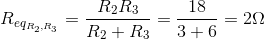
Next, use the voltage divider equation to find VR2:
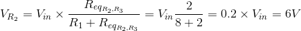
Additionally, the voltage across R2 and R3 is equal because these resistors are connected in parallel: VR2 = VR3.
According to Kirchoff’s Current Law (KCL), the sum of all currents entering a node equals to the sum of all currents leaving it. The current IR1 in this simulation divides into two - IR2 and IR3 – and is, thus, equal to their sum: IR1 - IR2 - IR3 = 0. In other words, IR1 = IR2 + IR3.
By Ohm's Law, current through each resistor will be equal to the voltage across the resistor divided by its resistance. This simulation shows that current flows through the path of least resistance (there is more current flowing through R2 than R3): V = IR1 = I2R2 = I3R3.
This model also lists the amount of power dissipated by each resistor. You can verify that the power dissipated equals to the current running through a resistor times the voltage across it.
Experiments
- Equate R2 and R3 values. What is the current through these resistors in relation to the current through R1 now?
- Change the R2 or R3 value to zero ohms. What is the current through the remaining two non-zero resistors now?