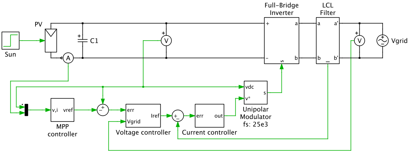
Single-phase PV inverters are commonly used in residential rooftop PV systems. In this application example, a single-phase, single-stage, grid-connected PV inverter is modeled. The PV system includes an accurate PV string model that has a peak output power of 3 kW. The control system comprises three control loops: a maximum power point (MPP) controller, a voltage controller and a current controller. These can be seen in the circuit diagram below. The outer control loop is a MPP controller that ensures maximum power is extracted from the PV string for a given insolation level. To do this, it calculates the optimal PV terminal voltage using a MPP algorithm known as dP/dV (incremental conductance) control. The voltage control loop, based on a type 2 controller, regulates the PV voltage to this optimal level by controlling the level of current that is injected into the grid. The innermost control loop, the current controller, sets the modulation index of the inverter such that the desired current is injected into the grid. The current controller is based on a PR controller with a resonant frequency of 50 Hz to ensure no tracking error is present. A damping resistor is included in the output LCL filter to ensure stable operation of the current controller.

Requirements
PLECS Blockset
- PLECS Blockset 3.4 or newer
- MATLAB 7.5 (R2007b) newer
PLECS Standalone
- PLECS Standalone 3.4 or newer
Download
You can download the example models for PLECS Blockset here and for PLECS Standalone here.
