Space vector control is a popular technique used in the control of motor drives or three-phase rectifiers since it offers reduced switching losses and better utilization of the DC bus compared to conventional PWM control. This PLECS demo model demonstrates space vector control of a three-phase boost-type rectifier.
Control
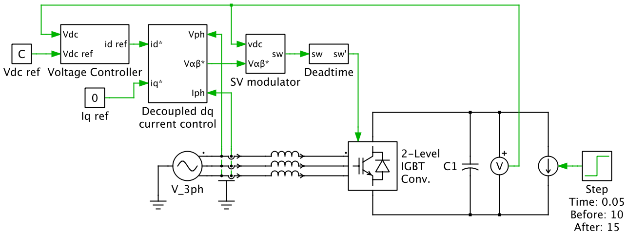
The control goals for the three-phase boost rectifier are to draw sinusoidal current from the input supply, vn, and to regulate the output voltage, VDC. Current control is achieved using an inner current control loop that measures the phase current, In, and controls the inductor-neutral voltage, vn1, to force the phase current to track its reference value. The current reference is provided by outer control loops that implement DC voltage and power factor control.
With space vector control, the inductor-neutral voltage is controlled as a vector quantity in the αβ or dq domains. In this example, control is performed in the dq domain. The advantage of dq control is that AC quantities become DC quantities in the dq domain. Thus no tracking error exists when using a PI controller to regulate the AC input current.
The reference AC voltage vector is generated by time-averaging the available switching vectors. Two popular modulation strategies have been implemented in the space vector modulator: an optimal modulation strategy that minimizes the switching losses and a symmetrical modulation strategy that minimizes the THD. A deadtime component has also been included to simulate the effect of switching delay when changing the switch state of a rectifier leg.
Implementation
The Space Vector Modulator block in the PLECS component library is implemented using a single C-Script block at its core. The C code written in the block does both detection of the operating sectors and the timing calculations for the switching vectors. The inherent sample time of the C-Script block is employed using a hybrid discrete-periodic and discrete-variable time step setting. This means that the block is executed at a fixed switching frequency, as well as major time steps that vary in time between these intervals and that are based on the on-times of the switching vectors calculated internally.
Download
Further documentation in PDF format can be downloaded here. Demo models for this application example are provided inside both PLECS Blockset and PLECS Standalone.