This PLECS demo model shows a high-speed salient permanent magnet machine drive based on Direct Flux Vector Control (DFVC).
Contrary to the more traditional rotor frame current regulation, DFVC operates in a synchronous frame that is aligned with the stator flux, in which flux and torque can be controlled directly by means of two basic PI regulators. This direct flux control is less dependent on an accurate knowledge of motor parameters and is particularly well suited for operating a machine in flux-weakening mode.
Electric and machine model
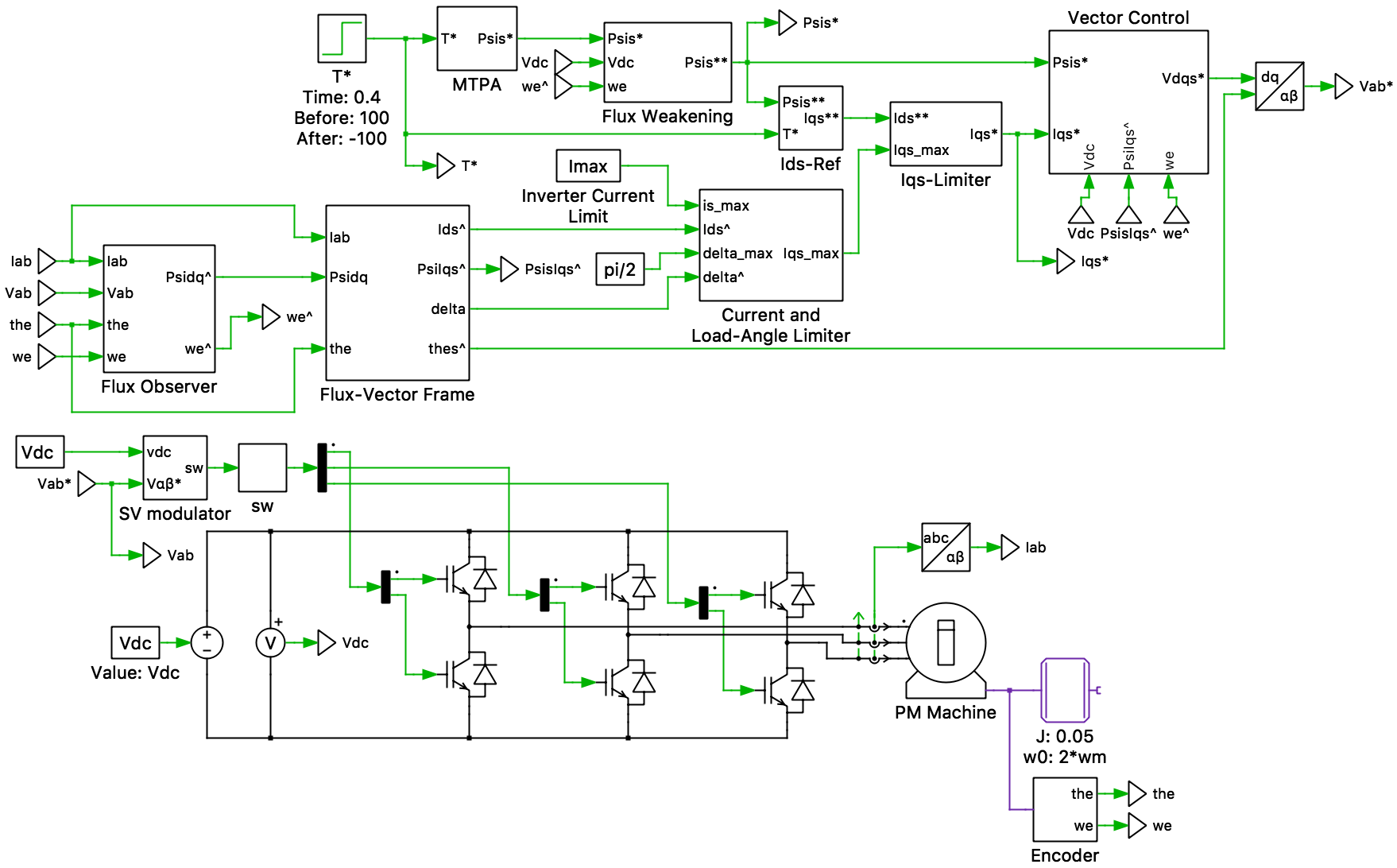
The voltage-source inverter (VSI) is modeled as an ideal three-legged bridge with a stiff DC supply. The six IGBTs are switched by means of a space vector modulator to realize the phase voltages commanded by the vector control. A three-phase motor current sensor and a DC link voltage sensor provide feedback to the control algorithm.
The electric machine is of the permanent magnet assisted salient type with Ld > Lq. It is connected to a frictionless inertia as well as an idealized position and speed sensor.
Control
The input to the control system is the desired machine torque. In order to optimize the efficiency of the drive, the Maximal Torque Per Ampere (MTPA) block first determines the optimal flux level. Depending on the motor speed and DC link voltage the desired motor flux may have to be further reduced to respect the maximal available inverter voltage. This is achieved by the Flux Weakening block, which also ensures that there is enough voltage margin for the regulators to handle transients.
With the desired flux determined, the set-point for the torque producing current component Iqs* can be established. Its value may have to be further reduced to ensure that the inverter current limit is respected and the maximal load angle not exceeded. The limit value for Iqs* is generated by the Current and Load-Angle Limiter block, which also contains a basic PI controller.
The Vector Control block then compares the set-points of flux and current with the actual quantities and calculates the appropriate voltage vector to be applied to the machine. While the control of the flux is fully decoupled, the current control is affected by the flux level and motor speed. A feed-forward term is therefore required to assist the PI in the current/torque path.
Since the motor flux cannot be directly measured, its amplitude and angle must be estimated by means of an observer. The observed flux is a fusion of a current-based magnetic model and a voltage-based integration, with the former being dominant at low speeds where the integration may be inaccurate.
Simulation
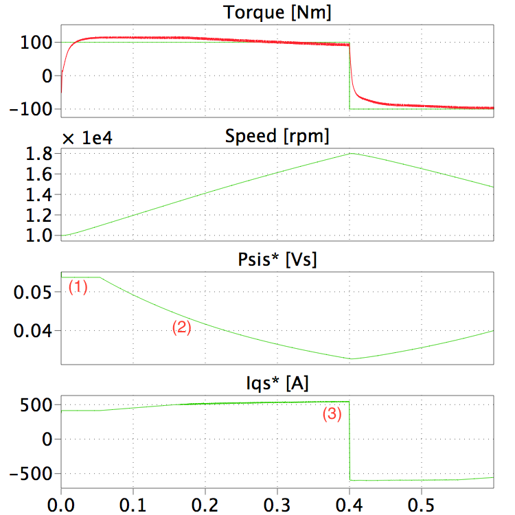
In the simulation the torque set-point of +100 Nm is achieved within the accuracy provided by the Flux Observer. For the first 50 ms (1 in the figure below) the torque can be produced at the ideal MTPA flux level. However, as the machine speed increases beyond the base speed, the flux level has to be reduced and the quadrature current increased (2), until eventually the current limit is reached (3). The torque set-point is subsequently reversed to –100 Nm, causing the machine to decelerate.
Try it
This model is available in the PLECS Demo Model library provided in both versions of PLECS.