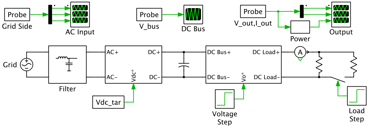
This PLECS demo model shows a grid-connected battery charger with cascaded AC/DC and DC/DC converters. The AC/DC converter is regulated by a digital PI controller to achieve power factor correction (PFC) and maintain the DC bus voltage at 300 VDC. The DC/DC converter is designed to provide a maximum 120 VDC output at a power rating of 1.4 kW.
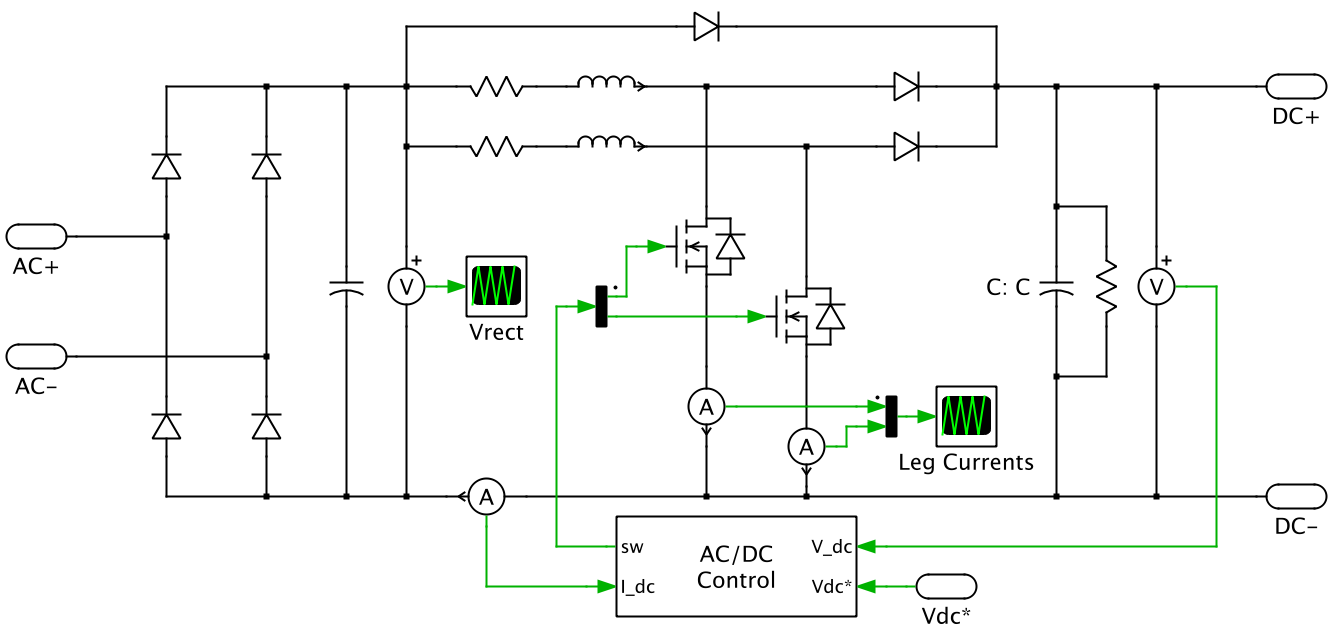
AC/DC Converter
The AC/DC converter is connected on the AC side via a single stage low pass filter. The topology is an interleaved PFC boost converter.
Digital control loops for voltage and current regulation are implemented to achieve power factor correction and regulate the DC side voltage to a desired level. The DC side voltage is sampled and compared to the target bus voltage setpoint. The digital voltage compensator with anti-windup sets a DC current setpoint. This DC setpoint is converted into an AC current setpoint to achieve PFC.
The current compensator determines a voltage setpoint, which is converted to a duty cycle. The duty cycle is then used by two symmetrical interleaved PWM blocks.
DC/DC Converter

Simulation
The AC/DC converter is regulated to maintain the bus voltage at 300 VDC. Initially the output voltage is regulated to 96 VDC, and at t=0.2 s, the output reference voltage is stepped to 120 VDC. This voltage step change causes the bus capacitor to sag as it is discharged to provide increased load current. The voltage is regulated back to the 300 VDC setpoint by the AC/DC converter. At t=0.35 s, the output reference voltage is maintained at 120 VDC and the load is doubled. The bus capacitor is again discharged by the increase in load current.

Try it
This model is available in the PLECS Demo Model library provided in both versions of PLECS.